Episode 06 - The Engineering Process (II)
by dodger-one
The Engineering Process (II)
After “Expensive Mistakes” let’s do a mix of engineering and … more mistakes 🤣
Batteries!
I wanted to keep as much as possible of the original Game Boy DMG spirit, and that involves standard AA batteries.
I have no idea how many AA batteries I burned through as a kid, but I’m pretty sure it was still fewer than a Game Gear owner would use in a single weekend 😈
Nowadays it’s much easier thanks to modern rechargeable batteries. I’ve been playing on the PicoDMG for almost two months since I finished the first unit, and I’m still using the same batteries. So no, this is definitely not a PicoDMG Game Gear edition 😜
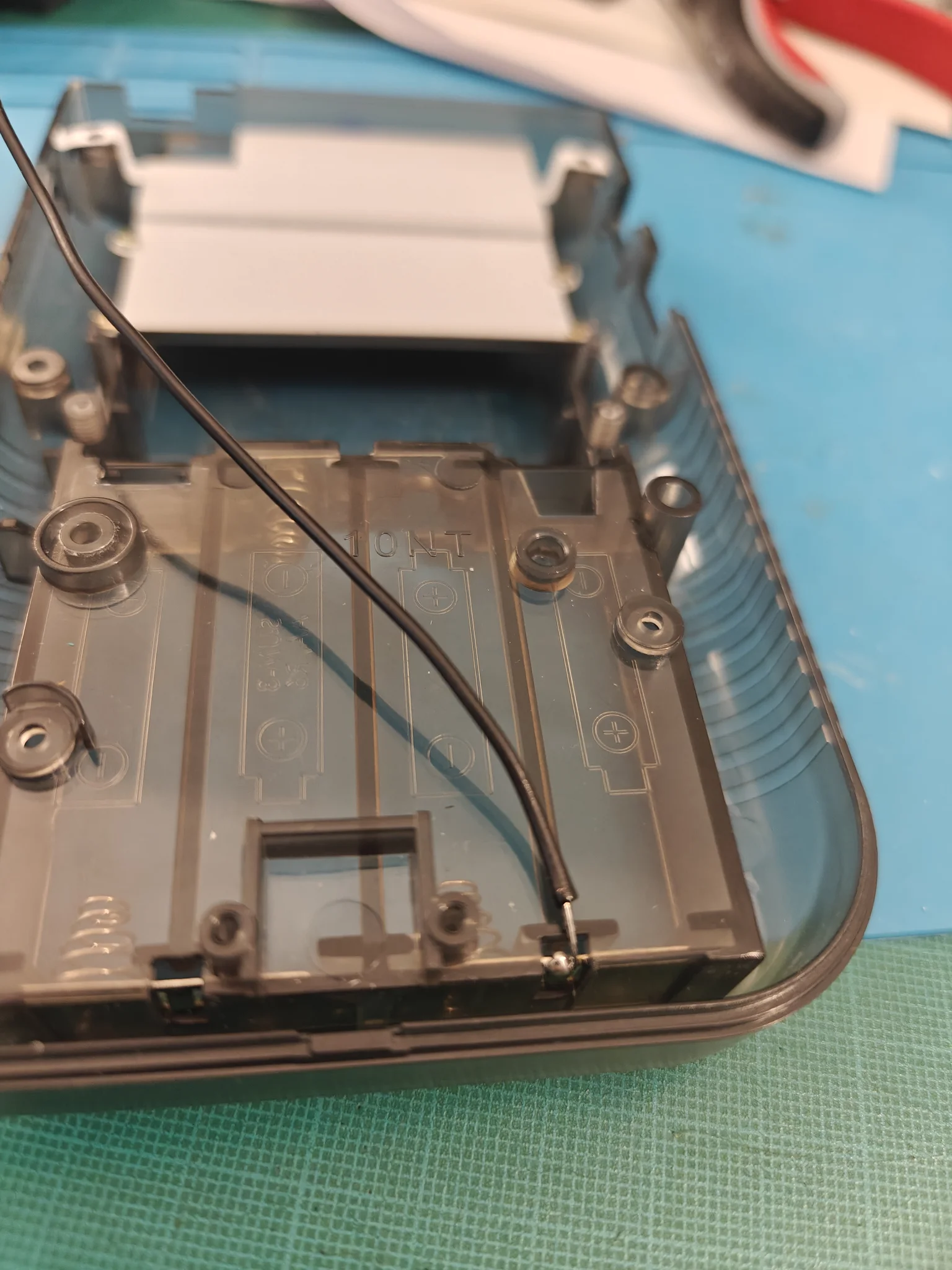
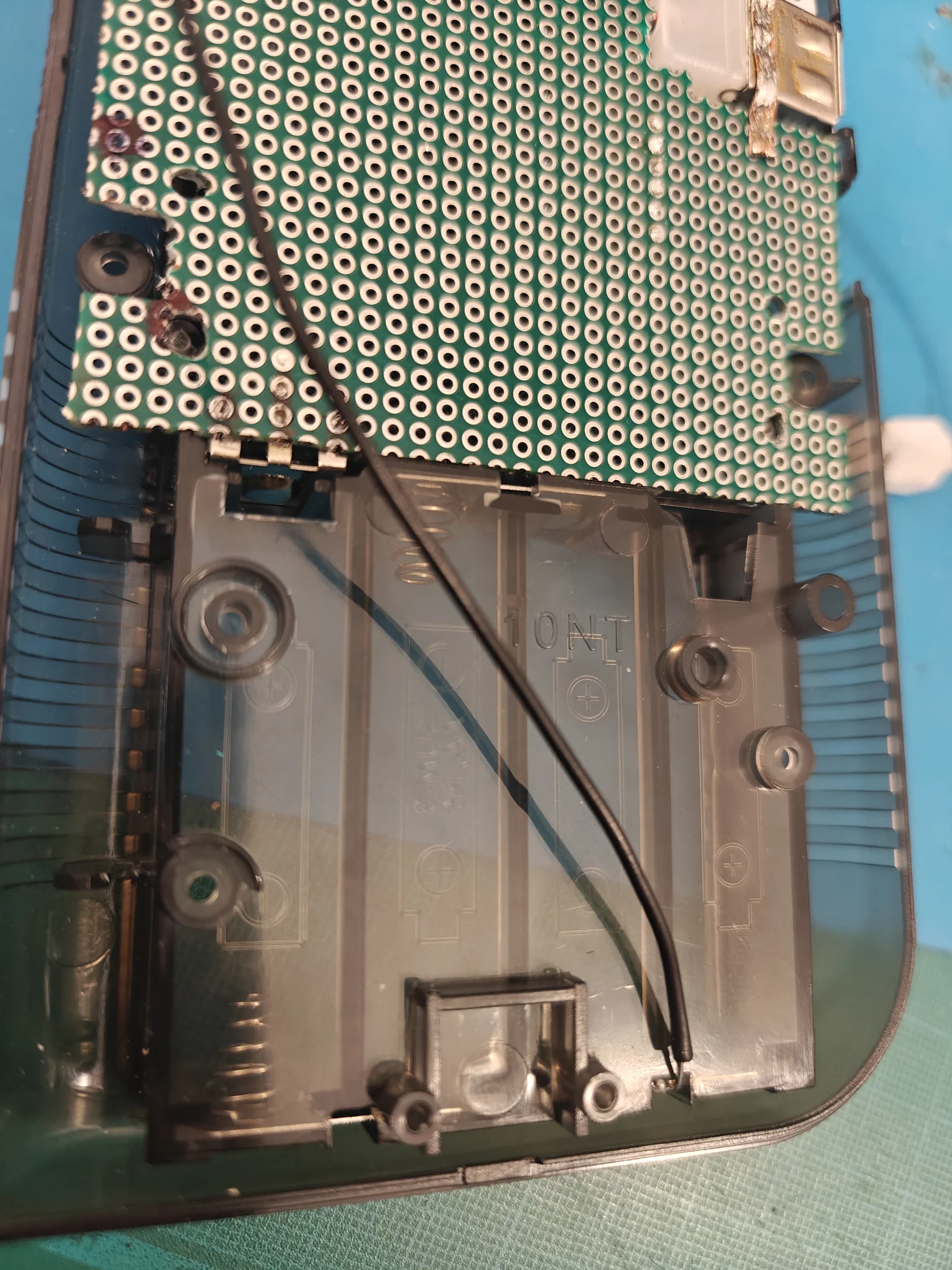
Here came the main power design decision for the PicoDMG: I would only use 3 out of the 4 AA batteries.
Why?
Because 4 × 1.5V is already above the RP2040/RP2350’s recommended 5V limit. With brand-new alkaline batteries, the voltage could even exceed 6V, giving you the wonderful RP2350 “toasted edition”.
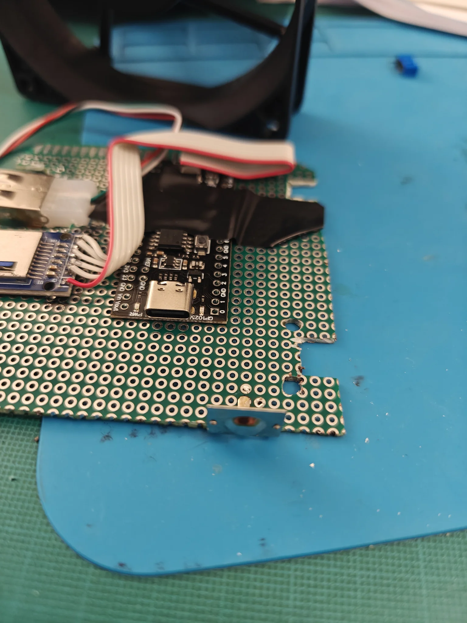
At first, I soldered an original battery terminal salvaged from a faulty Game Boy onto the custom perfboard:
And I took the positive rail from the last double terminal, meaning the PicoDMG will always be powered by only three batteries, regardless of whether I install three or four AAs:
This is how I would have liked to build it.
Of course, I was later forced to redesign everything to make it fit inside the shell.
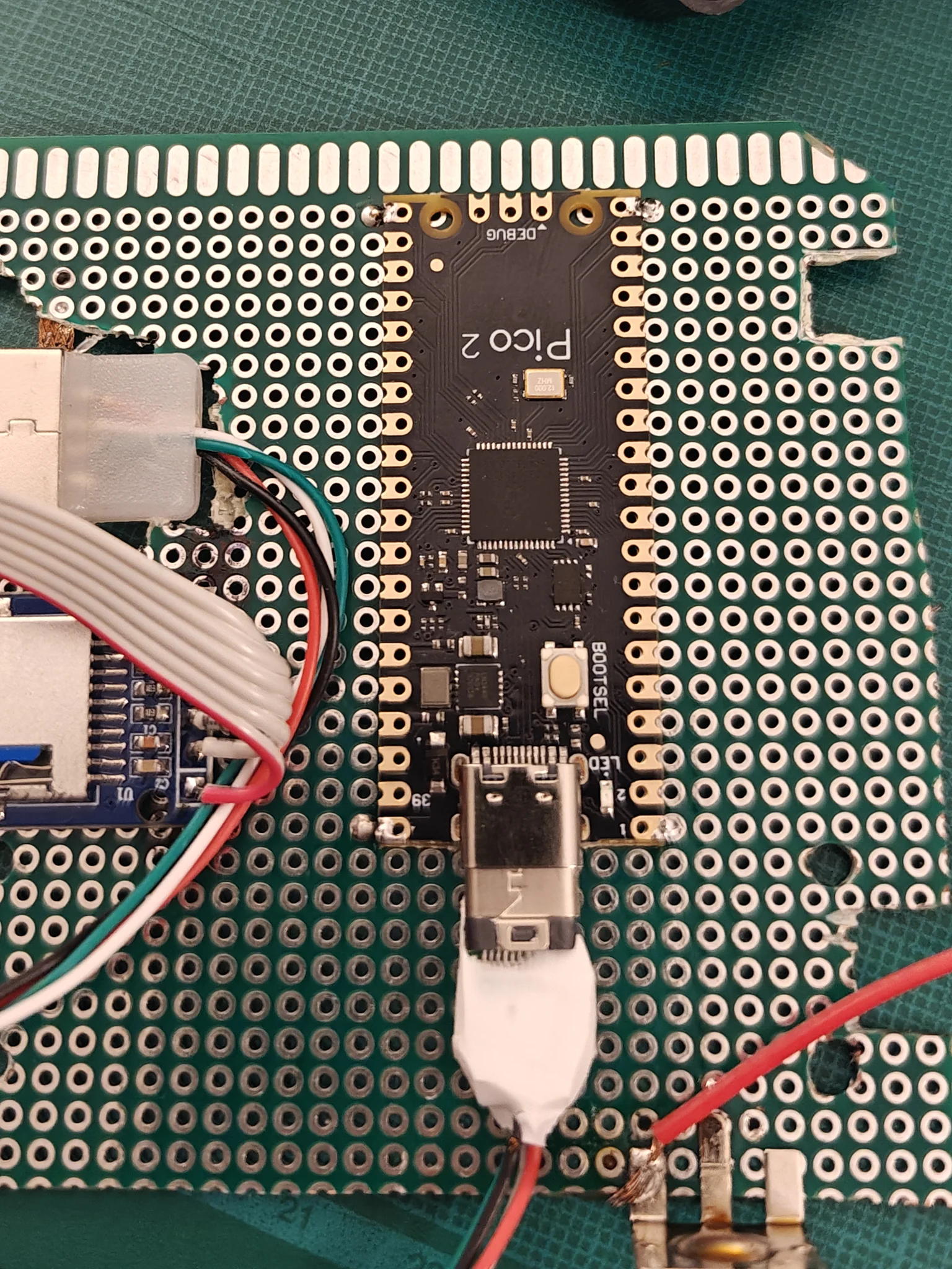
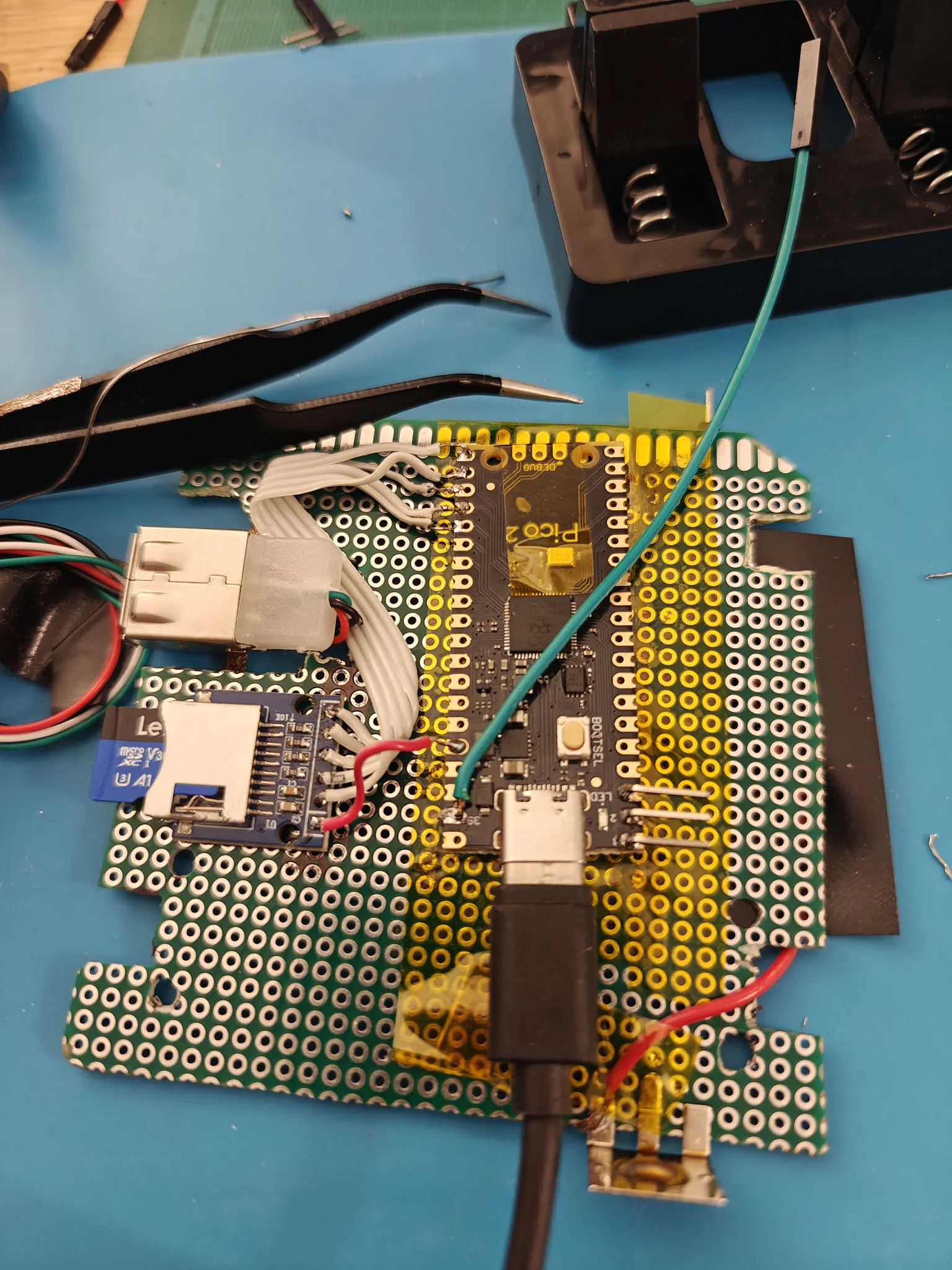
I used a breadboard connector so I could quickly plug and unplug the board.
As you may have guessed by now, this also proved unusable later…
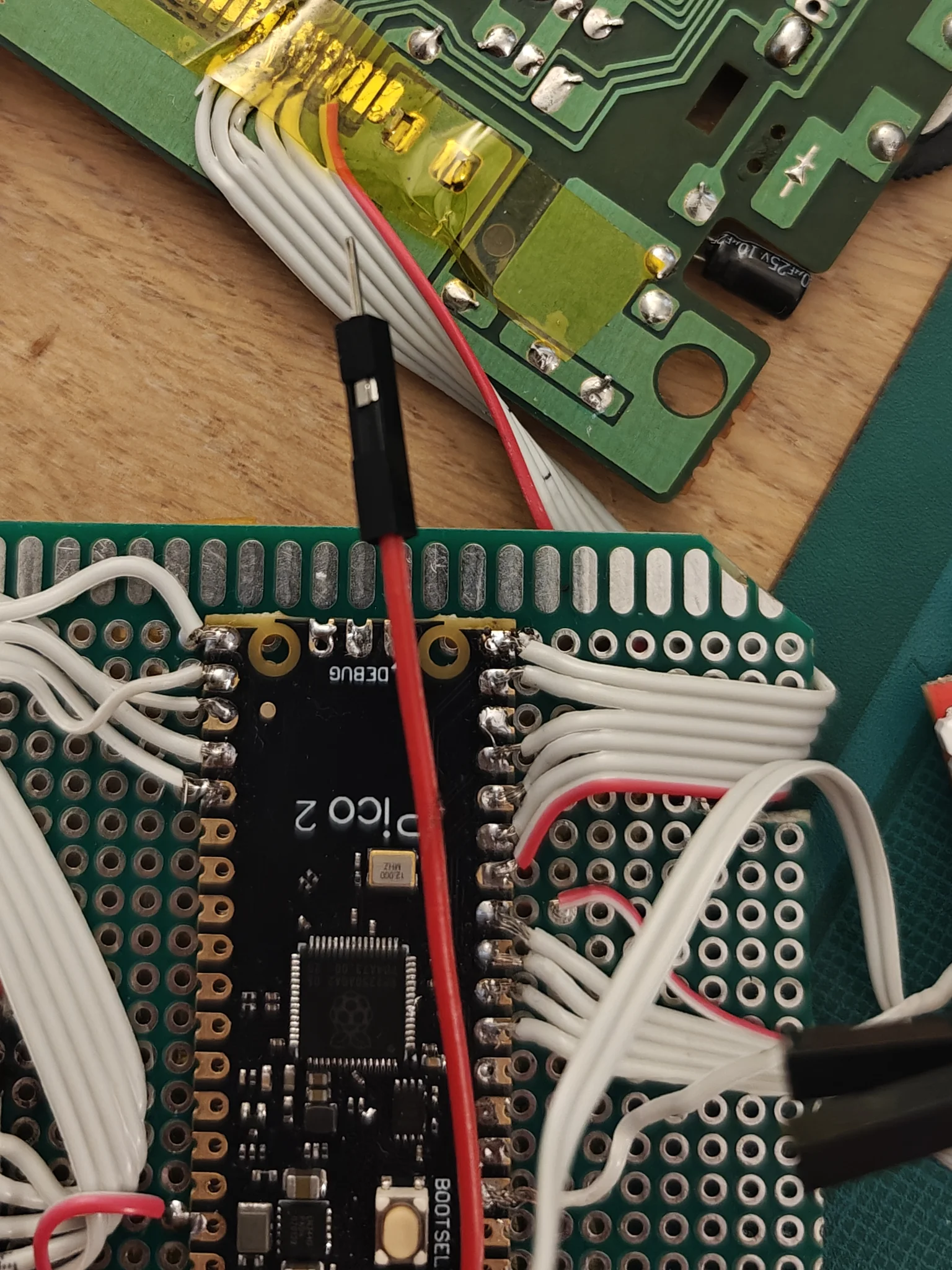
Wiring
Some awesome wiring pictures are coming:
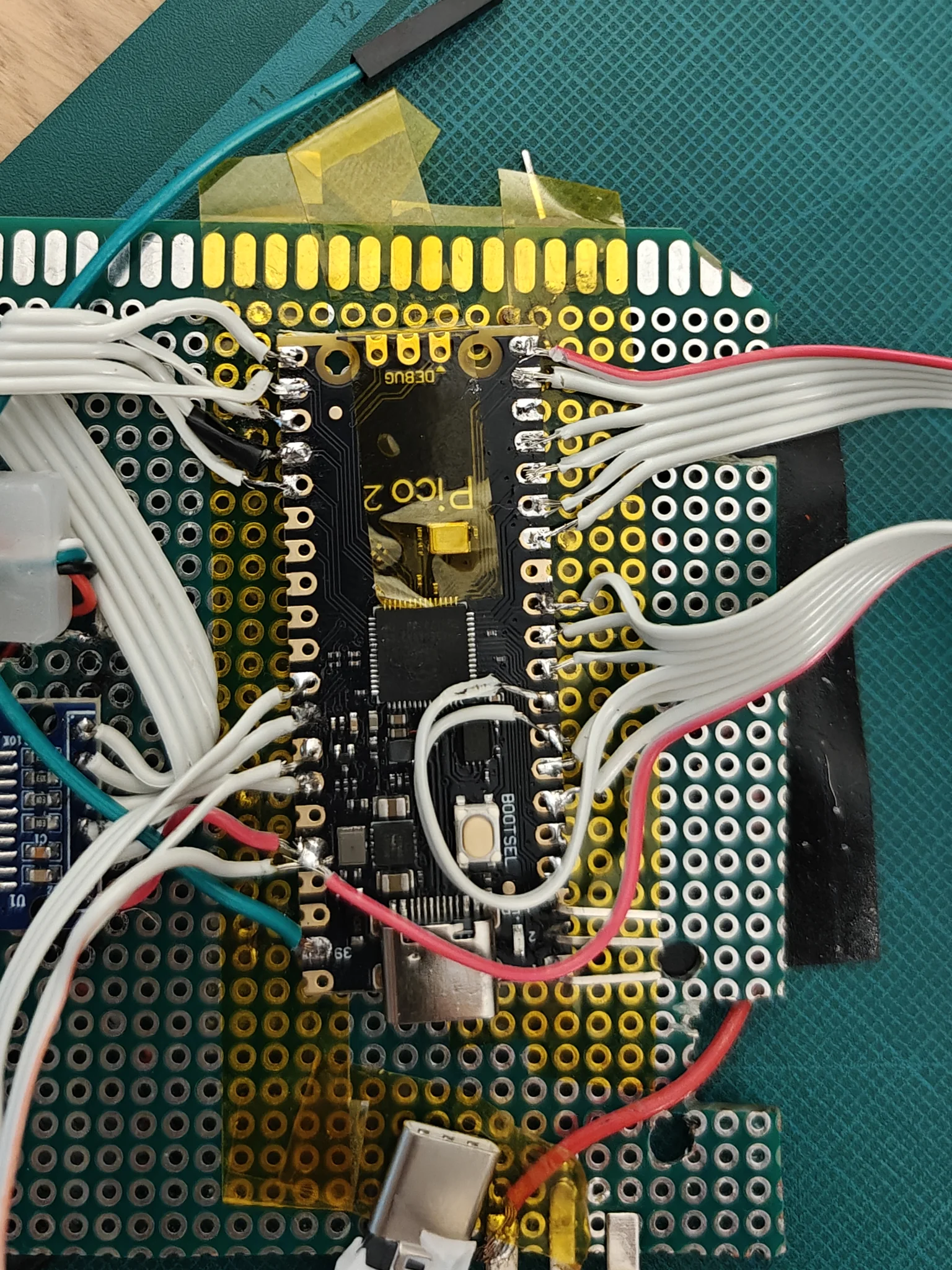
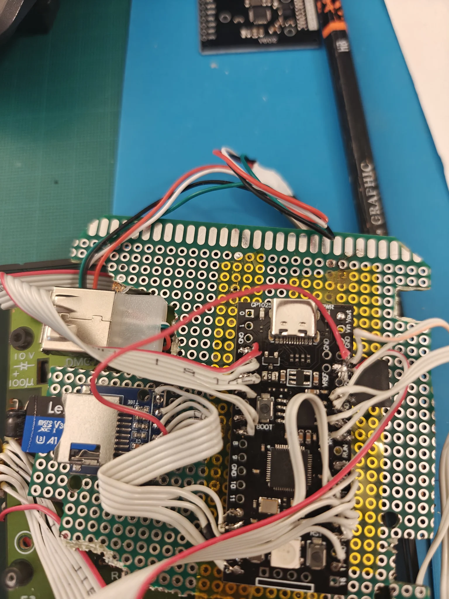
And final tests:
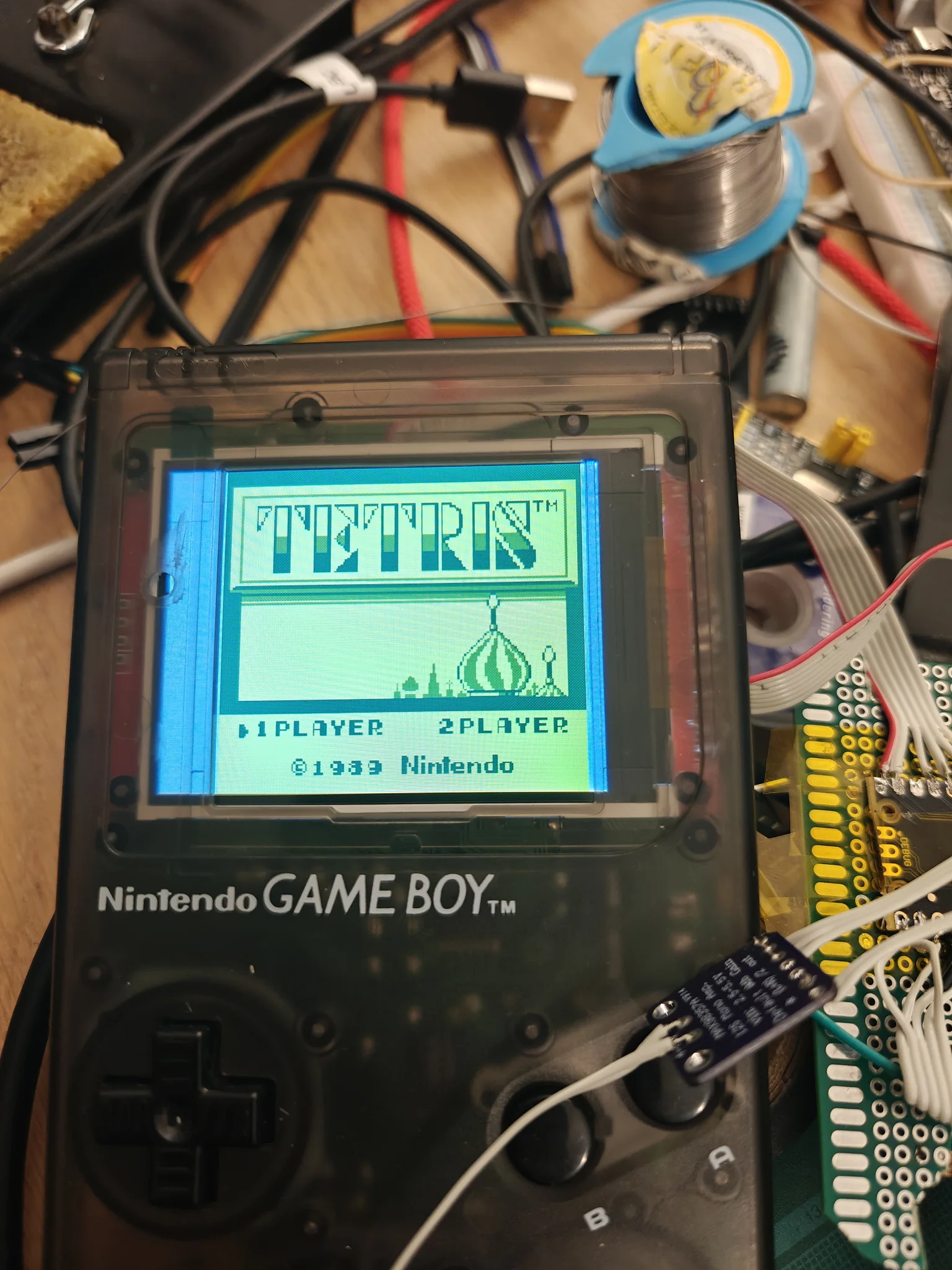
The camera completely failed to focus on the PicoDMG, but here’s the test video anyway:
USBc connector
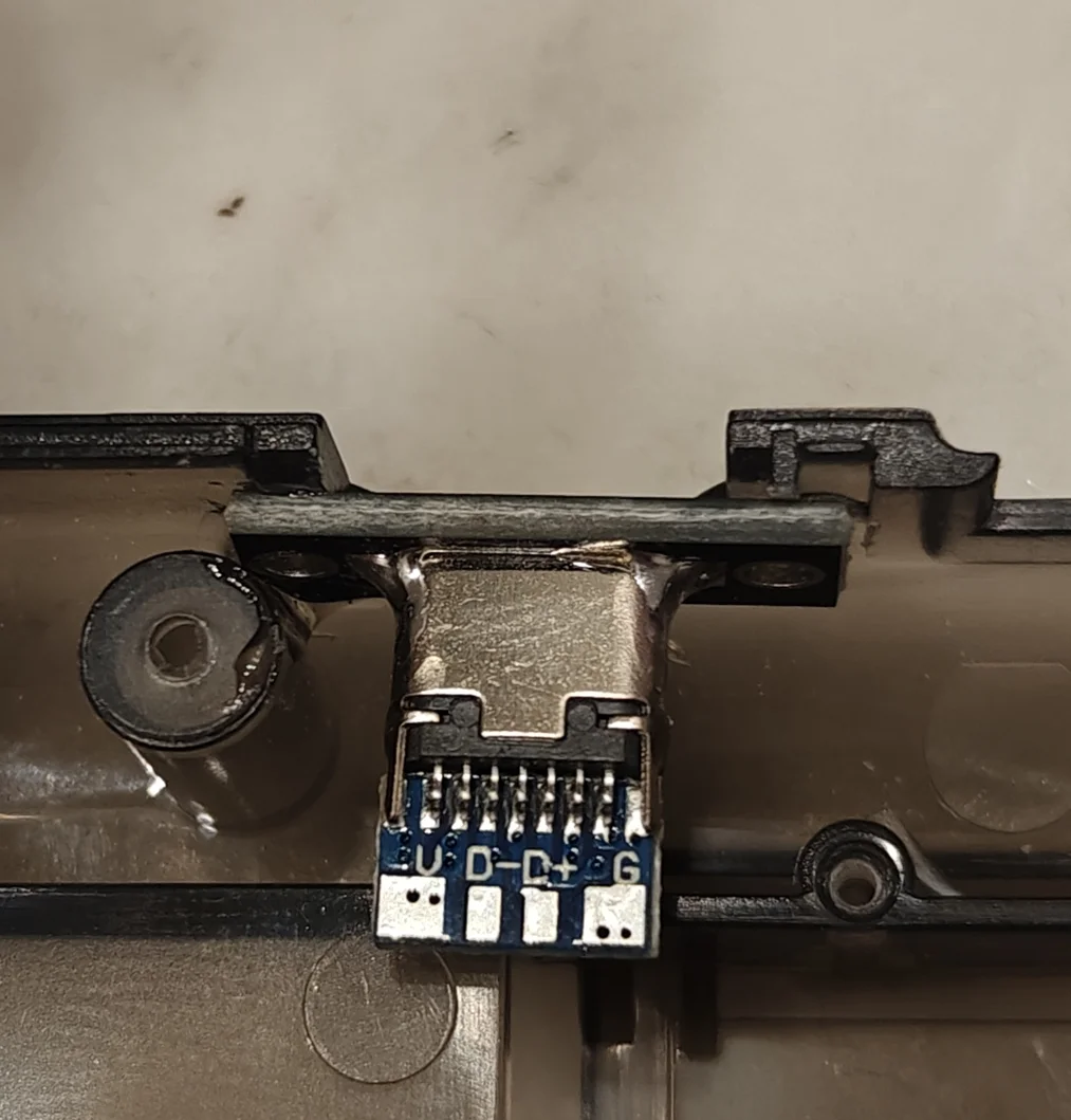
As I realized that using a USB-A connector inside the shell would consume far too much space, I decided to purchase a simple 4-pin USB-C connector (USB 2.0 only).
This turned out to be the right decision.
I simply glued it to the shell using some “extremely strong” adhesive. It required a bit of cutting, but it was easy to install and fits perfectly.
Buttons wiring issue
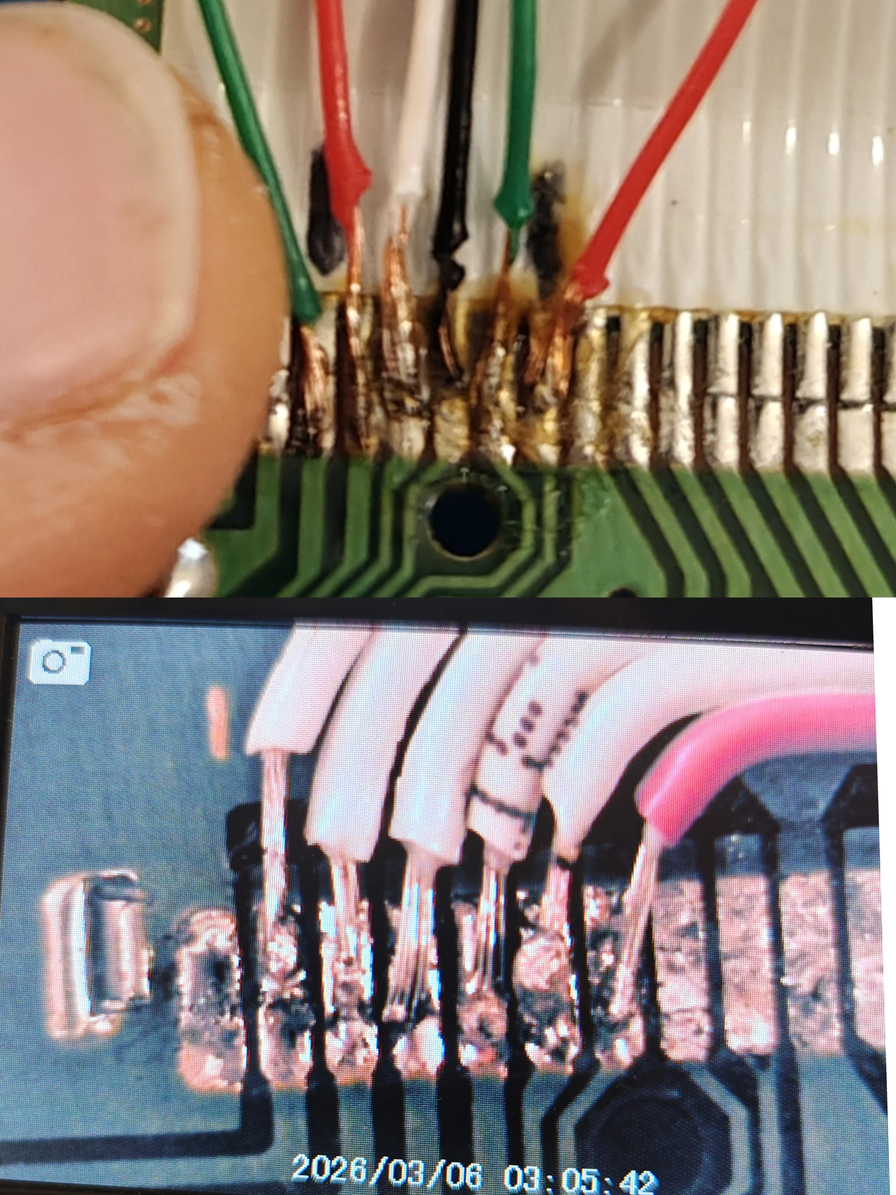
I realized that the DMG-LCD-01 button ribbon was wrong 🤣 I made a mistake, instead of begin wiring at position 4 I began at position 2 😂
So I have to re-wire that part. Here’s a picture taken on the microsocope comparing original testing wiring with the “definitive but wrong” wiring:
I realized that the DMG-LCD-01 button ribbon wiring was wrong 🤣
I made a mistake: instead of starting at position 4, I started at position 2 😂
So I had to rewire that entire section.
Here’s a microscope picture comparing the original test wiring with the “final but wrong” version:
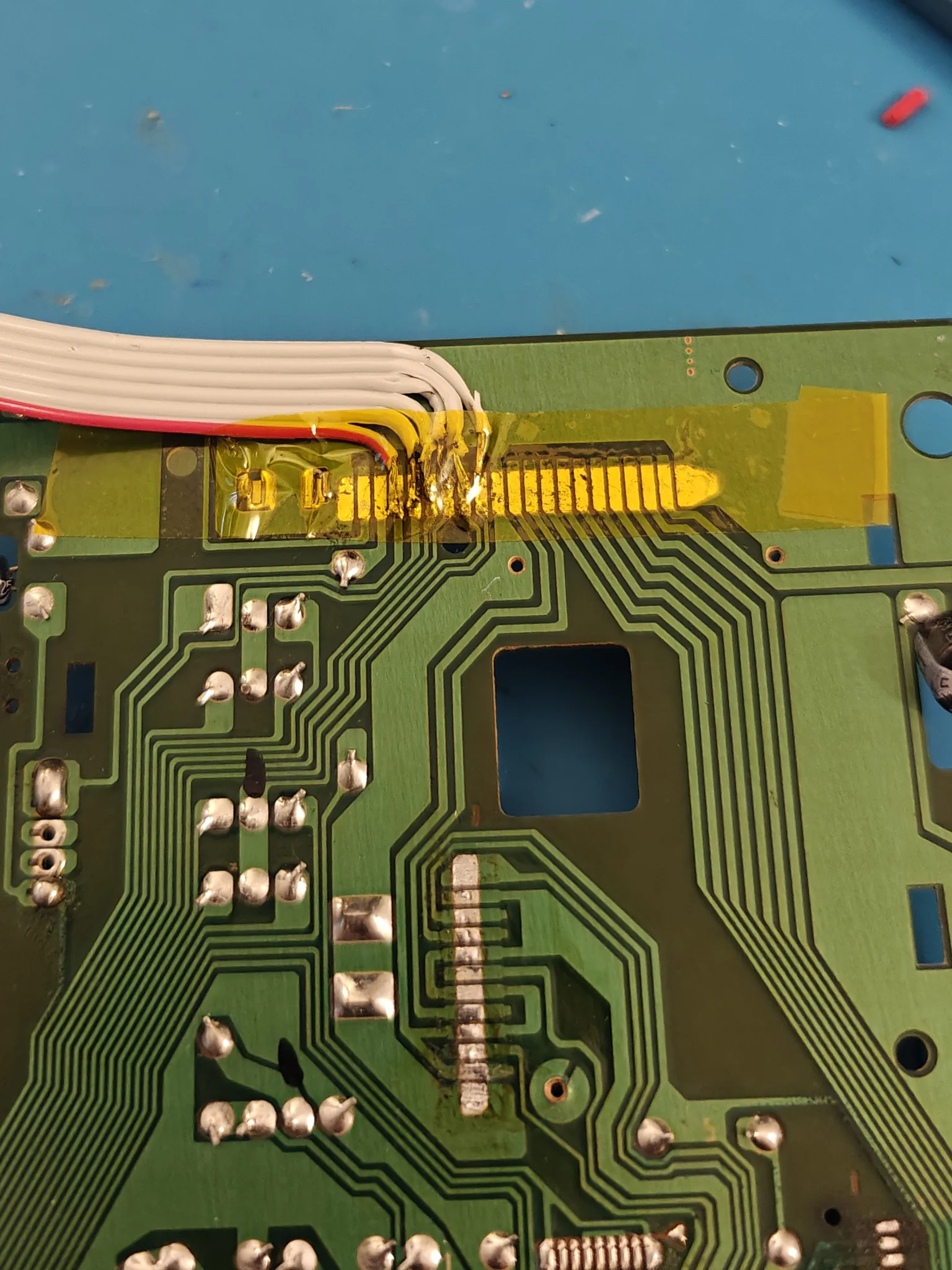
And the final good wiring:
Another Expensive fault (not mistake this time)
At this stage, the RP2350 suddenly stopped working.
- No CDC device.
- No boot.
- Sometimes it would enter programming mode, but only about one out of every ten attempts.
This resulted in a huge waste of time.
I checked the wiring for shorts and crossed signals, measured voltages, investigated the emulator, and basically questioned everything.
I spent almost a full week debugging before finally realizing that the RP2350 itself was faulty.
So… /cry
Remove all the wiring.
Start over.
Install a new RP2350.
Some pics coming (maybe you’ll see some tears over the table)…
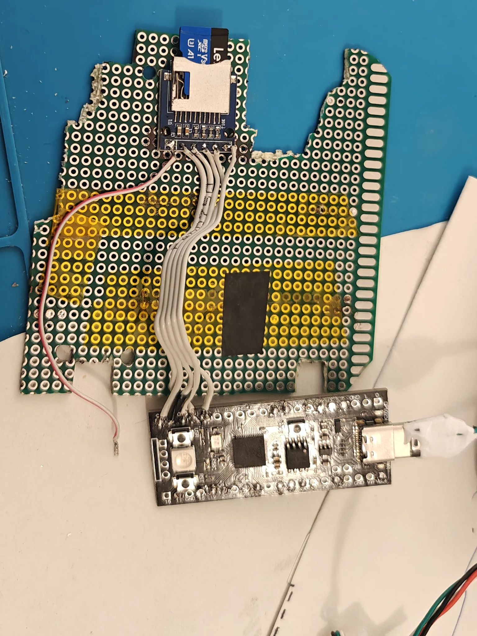
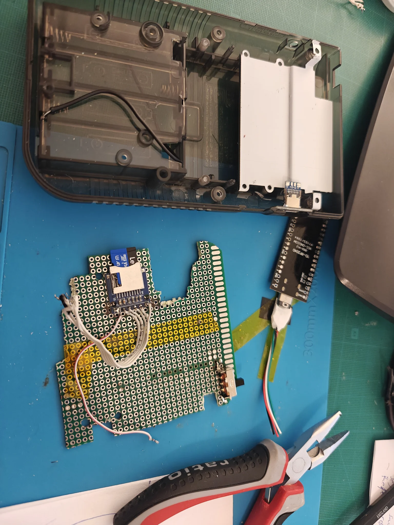
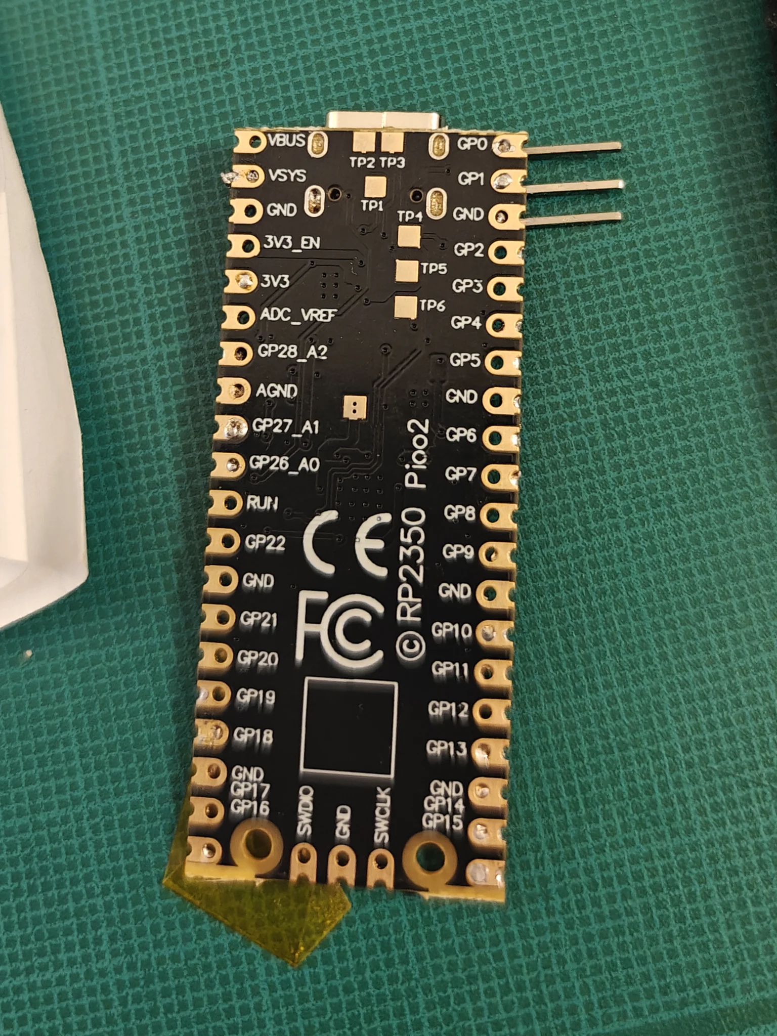
Fortunately, replacing the RP2350 solved the issue completely, proving once again that sometimes the problem really is the hardware.
Bonus Fail
This is a video from my latest tests using the Rust version of the emulator. After this I just give up 🤣